Rex Crayne
"Hyperloop Bogie"
5.1 Dimensions
5.1.1 Top-Level Design Summary
The stability bogie is designed as a single unit which will compensate for both lateral and vertical deviation in the test track. The stability bogie is designed to slide over the SpaceX track I-beam and hold at 6 points of contact. The vertical stability wheels sit on top of the flange of the I-beam and the lateral stability wheels touch either side of the web of the I-beam. Two stability bogies at either end of the pod ensure no significant lateral or vertical deviation in the pod’s trajectory.
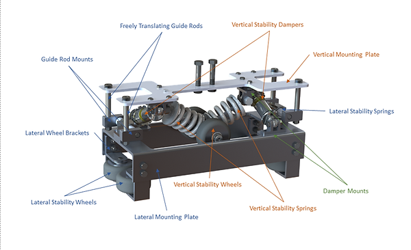
Figure 1: Stability Bogie with Major Part Labels
The bogie is composed of two independent systems: Vertical and Lateral Stability. These two subsystems are linked together by four guide bolts which are rigidly connected to the vertical mounting plate. The guide rods attached to the vertical stability mounting plate can freely translate through the rod mounts attached to the lateral stability system. This allows the two systems to move independently of one another.
The two systems are also linked by two small shock absorbers which are connected to the vertical and lateral mounting plates. This orientation of the dampers provides damping to both lateral and vertical stability. The vertical stability system smooths vibrations and undulations of the pod caused by deviations in the flange of the I-beam. The lateral stability system mitigates these effects from the web of the I-beam.
For increased vibration damping, a sheet of rubber will be adhered to the top of the vertical mounting plate. The rubber padding will absorb vibration and protect the frame and vertical mounting plate from contact damage. In the case that the stability bogie is overloaded, protective padding will be added to the underside of the lateral mounting plate to ensure no metal-to-metal contact. Rubber end-caps will be added to the vertical guide rod mounts.
5.1.2 Overall Dimensions with Figures and Annotations
The overall envelope of the system was kept minimal to save space for other critical components while also incorporating guides, damping, and vibration control. The image below indicates critical dimensions of the stability bogie.

Figure 2: Overall Dimensions of Stability Bogie
5.1.3 Mass Breakdown of System
The total mass of one stability bogie is approximately 18 lbs. The majority of weight of the system comes from the vertical and lateral mounting plates as these are fabricated from solid pieces of aluminum. Weight reductions were added where appropriate, although the sheets were kept mostly intact to improve structural rigidity. As a weight-saving method, it was considered to remove one spring form each vertical spring assembly and replace with a bracket. However, both springs are necessary to ensure the maximum load on each spring is not reached.
5.2 Design Considerations
5.2.1 Limitations
The primary constraint on the stability bogie design was interface with the SpaceX I-beam. The geometry of the I-beam was supplied by SpaceX and used to determine width between lateral stability wheel and location of the vertical stability wheels with respect to I-beam location.
During braking, the stability bogie will be subjected to high stress due to load transfers. For a conservative estimate on loading conditions, it was assumed that the entire weight of the pod (estimated 350 lbs.) shifts to the front bogie.
The vertical stability springs were selected at a spring rate approximately 100 lbs./in. Based on these properties, a load of 350 lbs. would cause the frame to compress approximately 0.50 inches vertically. This load was selected as a conservative 100% load transfer to the front bogie. The vertical guide rod nuts are located .5 inches from the top surface of the lateral mounting plate, allowing enough clearance in case of overloading.
Track fluctuation was modeled to determine worst case loading on the bogie and oscillatory system behavior. An oscillation of .4 in. was assumed over every 10 ft. This model of the track fluctuation was used to determine minimum loading capacity of the damper.
5.2.2 Governing Equations
To understand how stability bogies will assist in damping vibration, it is useful to model the entire pod system as a mass-spring-damper. The total mass of the pod is combined and sits on top of the 4 vertical stability springs. A sinusoidal forcing input which originates from deviation in I-beam flange and web thickness drives vibrational behavior. The governing equations for vertical and lateral pod movement are as follows:

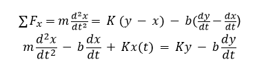
Where m represents mass of the entire pod, K represents an effective (combined) spring constant, b represents viscous damping, and y is the sinusoidal input forcing function.
To model system behavior, an effective viscous damping coefficient (b) must be experimentally determined. After this property is understood, various simulations can be performed to understand how the pod will behave under different vibration scenarios.
5.2.3 Preliminary Calculations
To maintain a compact system, lateral and vertical stability wheels were selected at a diameter of 3.25 in. At a maximum speed of 350 MPH, the wheels and bearings rotate at 36,235 RPM. Bearings must be sized to accommodate these high speeds. (See appendix A.5 for a detailed calculation)
To understand the vibrational input from the track rail to the stability bogie, one can examine the tolerance on the flange of the I-beam. The I-beam can deviate a maximum of 0.4” every 10 ft. To estimate a worst-case scenario, it was assumed that every 10 feet the tolerance will vary by the maximum amount. This creates a consistent sinusoidal forcing function into the system. At 350 MPH, a cycle in which the track will raise and then lower 0.4” over 20 ft. will occur every 0.039 seconds. This translates to an input frequency of approximately 25 Hz. (See appendix A.5 for a detailed calculation).
5.3 Engineering Calculations and Justification
5.3.1 Predicted Oscillatory Behavior
Analysis of vibration dynamics of the system are critical to minimizing vibrations to protect critical equipment like the control system and battery box.
Understanding the natural frequency of the system is critical to peak performance and vibration mitigation in the system. To find the natural frequency, the pod was modeled as a simple mass on 6 vertical springs each with a stiffness of 100 lbs./in. The natural frequency was found for several masses using the equation:
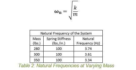
The worst-case scenario track undulation at max speed of 350 MPH would cause a forcing function at a frequency of approximately 25 Hz. Assuming a worst-case track condition, the pod will pass through, but not operate at the resonant frequency of the system. Realistically, the track will not deviate at such a high rate. The track should be much smoother and therefore cause far less disturbance.
To understand system response to vibration input, the pod was modeled as a mass-spring-damper system using Simulink by Mathworks. The stability bogie as well as the springs and dampers attached to the drive wheel were modeled as linear spring and dampers. To achieve a general overview of system performance, several simplifying assumptions were made. First, the pod was modeled as a simple, uniform mass. Second, the oscillatory movement was constricted to only one degree of freedom. Since the interest of the study was to determine appropriate damper coefficients, these assumptions are appropriate.
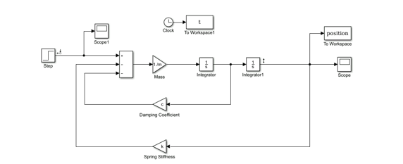
Figure 3: Simulink Model of Pod
The system was excited via a step input with a force of 600 lbs. at critical damping to simulate a change in I-beam flange height due to tolerances. The selected spring rate was approximately 100 lbs./in for each of the six springs. At this force, the system deflected 7 mm or 0.276 inches.
At critical damping, the settling time of the system was close to 1 second. To improve settling time and energy absorption, the damping ratio was changed from 1 to 0.5. At this damping ratio, the system has a settling time of 0.22 seconds. A smaller damping ratio is acceptable as the oscillation amplitudes are small and much of the energy which would cause vibrations is absorbed by the dampers.
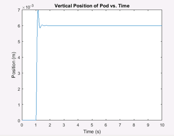
Figure 4: Step Response of Pod
A damping ratio of 0.5 for this submission yields a damping coefficient of 30 lbs./in. As there are six identical dampers used to absorb pod energy, each damper should have a high-speed damping value of 5 lbs./in.
5.3.2 Analysis and Explanation
Required Vertical Spring Stiffness: The required stiffness of the spring was derived based on the constraint that the pod should not compress more than 0.50” vertically under worst-case loading conditions. This will ensure that the pod will never compress low enough to touch against the I-beam. Based on the vibrational analysis, an appropriate spring constant for vertical stability is approximately 100 lbs.
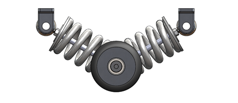
Figure 6: Vertical Stability Spring Assembly
Required Lateral Spring Stiffness: The lateral spring stiffness was determined such that at a deviation of 0.25 inches, one set of bogie springs together would provide a correcting force of 350 lbs. The selected springs must therefore have a stiffness of greater than 700 lbs./in. The selected springs provide a stiffness of 901 lbs./in.

5.3.3 Simulation Results
To ensure safety against yielding of mechanical components, finite element analysis was used analyze to critical components of the system. These major areas were the vertical guide bolts, the lateral mounting plate, and lateral wheel brackets.
Vertical Guide Bolts
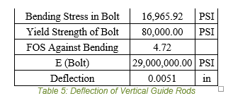
The maximum force encountered by the vertical guide bolts arises when the springs of the lateral stability system are fully compressed. The springs were sized to correct the pod in the event of a displacement: 350 lbs. applied to the center of mass. Thus, each spring will provide a force of 87.5 lbs. against the vertical guide rod. To simplify the FEA model, the rod mount was rotated sideways to accurately represent force applied to the bolt. FEA of this component results in a FOS of 3.68. Hand calculations also verified a FOS over 4. Stresses which are translated to the rod mount and vertical mounting plate were low compared to the stress in the bolt.
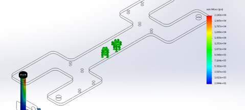
Figure 7: FEA Stress Plot for Vertical Guide Bolts
Lateral Stability Mounting Plate & Wheel Brackets
The maximum force seen on the lateral stability plate comes from worst case tolerance on the I-beam track. At a maximum deflection of .03125 in., it is estimated that each wheel would experience a normal force of 150 lbs. This force is applied to the lateral stability plate and lateral wheel mounting brackets. Simulation of this loading results in a FOS of 4.1.

Figure 8: FEA Stress Plot for Lateral Mounting Plate
Wheel Bracket
The maximum force experienced by the wheel bracket comes from deviation in I-beam thickness. At maximum thickness, the wheel assembly will be pushed out at a force of approximately 150 lbs. This force was divided between the two pin holes in the wheel bracket while the top face was fixed. The maximum stress occurred at the fillets on the top connecting point of the bracket. This study resulted in a FOS of 6.23.
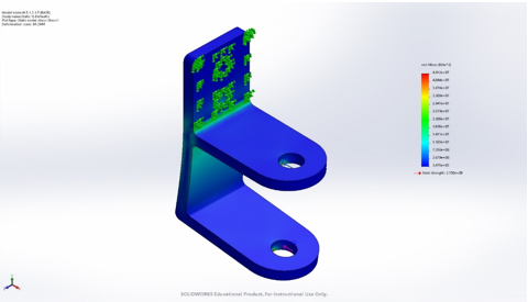
Figure 9: FEA Stress Plot for Wheel Bracket
5.3.4 Points of Failure
Bearings: Some of the critical components of the stability bogie is wheel bearings. Since the pod is moving at such a high speed and wheel radii are very small (1.75 in.) bearings must be able to withstand very high RPM. As such, high grade bearings must be selected and rigorously tested before they can be used in the pod. If the bearings cannot withstand the required angular velocity, they can overheat, seize, or otherwise fail. This could cause the pod to drag, lurch forward, or stop at a high rate.
To mitigate the effects of a potential bearing failure, spring stiffness in the vertical stability was chosen to be very high. Even in the event of a sudden stop, the stiffness of the vertical springs will not allow the lateral stability plate to strike the I-beam. Rubber sheeting on the bottom of the mounting plates serves as a failsafe against plate striking.
Wheels: Polyurethane wheels have been observed to fail catastrophically when subjected to high RPMs. At high speed of the pod, the rubber wheel could snap. High strength wheels will be selected and rigorously tested to ensure high strength. To mitigate the effects of this point of failure, sensitive components like the control system are isolated from the bogie and protected by plating and a case from debris.
5.4 Testing and Validation
5.4.1 Proposed Testing Procedure
5.4.1.1 Wheel Testing
Under high RPMs, polyurethane wheels have been found to spontaneously disintegrate. Such an event would prove catastrophic for a 350 lbs. pod traveling at 350 MPH. Therefore, testing on selected wheels is critical before full assembly testing can begin. Wheels will be tested using a custom dynamometer in which the wheel is mounted to a spindle rotating at the correct frequency behind a protective shield. The RPM will be adjusted to find the allowable angular velocity before the wheel rubber fails.
In the case that selected wheels cannot withstand the required angular velocity, geometry of the system may be modified to accommodate a larger wheel radius, or a different material will be selected. Aluminum wheels may offer greater strength, although their stiffness would create far more vibration than rubber.
5.4.1.2 Vibration Response
To determine how the system will behave under worst-case and expected vibration, the stability assembly should be tested under several different frequency inputs. Testing the stability table on a shake table is the best way to determine system response. The vertical mounting plate will be fixed and the bottom wheels of the assembly will rest on the shake table. The shake table will be allowed to move a maximum of .4 in. at varying frequencies. To simulate the lateral system response, the top plate will be fixed again, and the shake table will be programmed to oscillate sideways. This provide validation for natural frequency of the system as well as damping response under a repeated load. The major design goal is to avoid operating at natural frequency and mitigating system response at a range of operating frequencies.

Figure 10: Example of Shake Table Testing Apparatus
Selected shocks will also be validated using a shock dynamometer. The shock dynamometer will transduce applied force, velocity, and displacement of the shock under test loads. These attributes of the shocks will be measured, from which the shock kinetic energy, total energy, hourly energy capacity, shock force capacity, and damping coefficients will be derived to validate the performance of the shock with the preliminary engineering calculations.
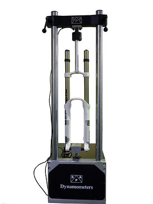
Figure 11: Shock Dynamometer
5.4.1.3 Bearing testing
Bearings must be tested to ensure efficient operation at high RPMs. The RPMs based on current system geometry is 36,235 RPM. High grade bearings must be selected to accommodate these speeds. Testing will entail attaching bearings to a wheel and loading into a custom dynamometer. This testing may not provide quantitative data about bearing efficiency, but will provide a qualitative test to determine if bearings will seize, fracture, or otherwise fail under loading.
5.4.1.4 I-beam sections
A mock I-beam section will be purchased as utilized to ensure proper tolerances of the fabricated stability assemblies. The web of the beam must fit between the lateral stability wheels with no room to wiggle and minimal squeezing to fit on. Excessive clearance will result in an unstable pod; a press fit will cause unacceptable radial loading and drag in bearings. If tolerances do not match specification, parts must be corrected.
5.4.1.5 Strain gauges and static loading
Static loading of critical components such as the vertical guide rods, lateral wheel brackets, and lateral mounting plate with strain gauges will be used to validate finite element analysis results. Each component will be mounted to a wooden testing frame (wood is acceptable as most loading conditions are moderate) and loaded using weights. Strain gauge data will be recorded and used to compare to FEA studies. FEA studies will either be validated or rerun to determine worst case loading conditions en route.
Appendix A.5
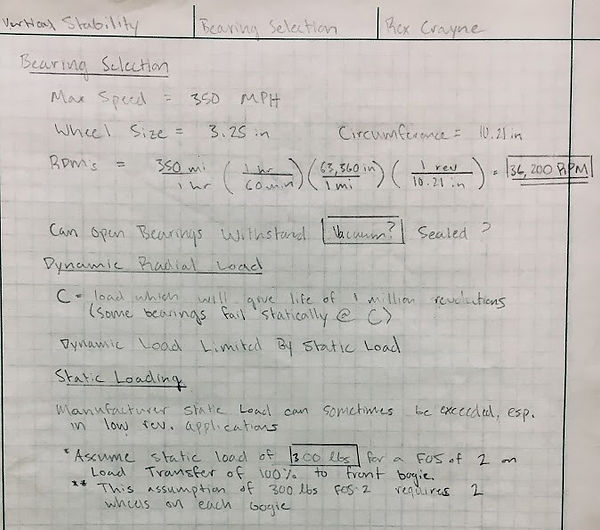
Figure 12: Required Bearing RPM Calculation
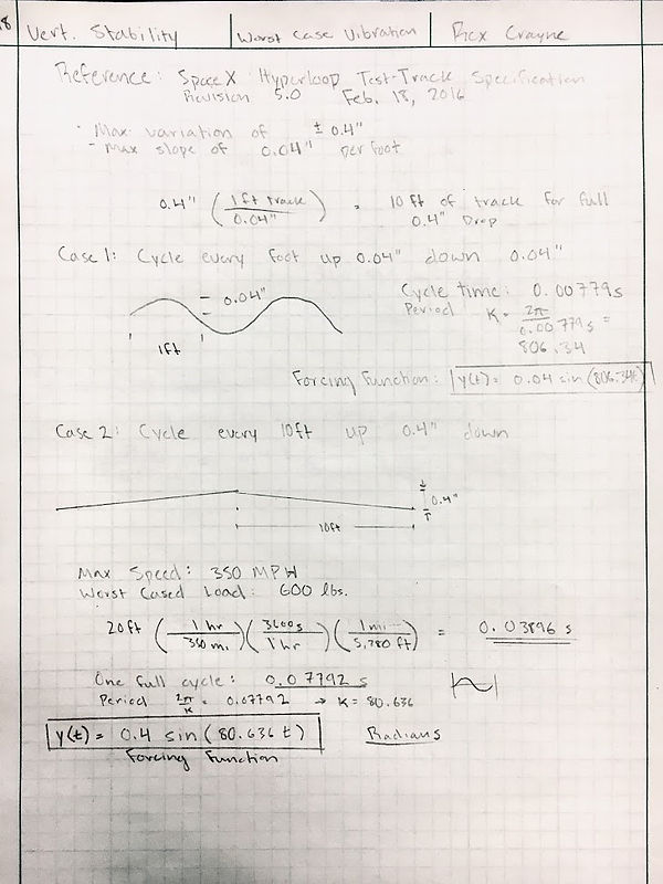
Figure 13: Worst-Case Vibration Calculation

Figure 14: Shock Absorber Formulas